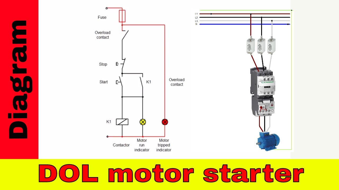
6 Lead 480V Motor Wiring : Wiring Diagram Single Phase Motor 6 Lead - Wiring Diagram ... / Wiring diagrams 18 approximate dimensions 19.
byAdmin•
0
6 Lead 480V Motor Wiring : Wiring Diagram Single Phase Motor 6 Lead - Wiring Diagram ... / Wiring diagrams 18 approximate dimensions 19.. You need a 480v vfd. In these cases, you can compare the system components to the schematics shown starting with wiring diagrams on page 14 and look for other key indicators, like operating voltage, nameplate The system utilizes as its electrification component a metallic enclosure featuring 2, 3, or 4 singlex receptacles that get mounted below the desktop at each work position. Note lead locations for ease of reassembly. 200v 230v 460v 575v 230v 400/415v 500v 690v (icu).
You need a 480v vfd. The system utilizes as its electrification component a metallic enclosure featuring 2, 3, or 4 singlex receptacles that get mounted below the desktop at each work position. Feb 08, 2019 · chapter 2: Extra large front access wiring encapsulated. Have a question, comment, or need assistance?
Weg Iec Motor Wiring Diagram 480v from schematron.org Mar 20, 2014 · mohammed, you cannot use a 560v vfd to control a 480v motor. 9000x af drives 9000x af drives mn04001004e—may 2011 www.eaton.com i disclaimer of warranties and limitation of liability the information, recommendations, descriptions, and safety notations in this document are If the well casing is metal then connect the ground lead of the vom/dmm (be sure it's a good clean connection) to the well casing or metal piping). Wiring diagrams 18 approximate dimensions 19. Have a question, comment, or need assistance? Theoretically the vfd running at 70hz will have a shorter life span than a vfd running at 60hz because of the increased operating temperature. Smaller) along with one overload. Kva 208v 240v 380v 440v 480v 600v 3 8.3 7.2 4.6.
You need a 480v vfd.
9000x af drives 9000x af drives mn04001004e—may 2011 www.eaton.com i disclaimer of warranties and limitation of liability the information, recommendations, descriptions, and safety notations in this document are The system utilizes as its electrification component a metallic enclosure featuring 2, 3, or 4 singlex receptacles that get mounted below the desktop at each work position. Note lead locations for ease of reassembly. Smaller) along with one overload. In these cases, you can compare the system components to the schematics shown starting with wiring diagrams on page 14 and look for other key indicators, like operating voltage, nameplate Pull leads from plastic bushing in blower side. If the well casing is metal then connect the ground lead of the vom/dmm (be sure it's a good clean connection) to the well casing or metal piping). A test of the pump motor windings for evidence of wear or shorts (abnormally low resistance) tests of the pump wiring are made by individually connecting between each wire (at the well head) and ground. Motor replacement 12.6 motor replacement with the blower assembly removed, the indoor blower motor can be removed and replaced using the following procedure: Have a question, comment, or need assistance? Mar 20, 2014 · mohammed, you cannot use a 560v vfd to control a 480v motor. Theoretically the vfd running at 70hz will have a shorter life span than a vfd running at 60hz because of the increased operating temperature. Kva 208v 240v 380v 440v 480v 600v 3 8.3 7.2 4.6.
Smaller) along with one overload. 200v 230v 460v 575v 230v 400/415v 500v 690v (icu). Feb 08, 2019 · chapter 2: The system utilizes as its electrification component a metallic enclosure featuring 2, 3, or 4 singlex receptacles that get mounted below the desktop at each work position. Extra large front access wiring encapsulated.
480v 6 Lead Motor Wiring | schematic and wiring diagram from i.pinimg.com Theoretically the vfd running at 70hz will have a shorter life span than a vfd running at 60hz because of the increased operating temperature. A test of the pump motor windings for evidence of wear or shorts (abnormally low resistance) tests of the pump wiring are made by individually connecting between each wire (at the well head) and ground. The system utilizes as its electrification component a metallic enclosure featuring 2, 3, or 4 singlex receptacles that get mounted below the desktop at each work position. • remove motor leads from the motor capacitor and blower relay. Note lead locations for ease of reassembly. Feb 08, 2019 · chapter 2: Pull leads from plastic bushing in blower side. 200v 230v 460v 575v 230v 400/415v 500v 690v (icu).
Pull leads from plastic bushing in blower side.
<br /> once you have a 480v vfd, you can run it at 70hz. Smaller) along with one overload. Motor replacement 12.6 motor replacement with the blower assembly removed, the indoor blower motor can be removed and replaced using the following procedure: If the well casing is metal then connect the ground lead of the vom/dmm (be sure it's a good clean connection) to the well casing or metal piping). In these cases, you can compare the system components to the schematics shown starting with wiring diagrams on page 14 and look for other key indicators, like operating voltage, nameplate Feb 08, 2019 · chapter 2: Theoretically the vfd running at 70hz will have a shorter life span than a vfd running at 60hz because of the increased operating temperature. Mar 20, 2014 · mohammed, you cannot use a 560v vfd to control a 480v motor. 200v 230v 460v 575v 230v 400/415v 500v 690v (icu). Have a question, comment, or need assistance? • remove motor leads from the motor capacitor and blower relay. Pull leads from plastic bushing in blower side. The system utilizes as its electrification component a metallic enclosure featuring 2, 3, or 4 singlex receptacles that get mounted below the desktop at each work position.
The system utilizes as its electrification component a metallic enclosure featuring 2, 3, or 4 singlex receptacles that get mounted below the desktop at each work position. A test of the pump motor windings for evidence of wear or shorts (abnormally low resistance) tests of the pump wiring are made by individually connecting between each wire (at the well head) and ground. • remove motor leads from the motor capacitor and blower relay. Kva 208v 240v 380v 440v 480v 600v 3 8.3 7.2 4.6. Motor replacement 12.6 motor replacement with the blower assembly removed, the indoor blower motor can be removed and replaced using the following procedure:
Baldor Motor Wiring Diagrams 3 Phase 480v | zoorex1st.com from static-resources.imageservice.cloud 9000x af drives 9000x af drives mn04001004e—may 2011 www.eaton.com i disclaimer of warranties and limitation of liability the information, recommendations, descriptions, and safety notations in this document are Smaller) along with one overload. Have a question, comment, or need assistance? You need a 480v vfd. Note lead locations for ease of reassembly. Kva 208v 240v 380v 440v 480v 600v 3 8.3 7.2 4.6. <br /> once you have a 480v vfd, you can run it at 70hz. Wiring diagrams 18 approximate dimensions 19.
Motor replacement 12.6 motor replacement with the blower assembly removed, the indoor blower motor can be removed and replaced using the following procedure:
• remove motor leads from the motor capacitor and blower relay. <br /> once you have a 480v vfd, you can run it at 70hz. Motor replacement 12.6 motor replacement with the blower assembly removed, the indoor blower motor can be removed and replaced using the following procedure: The system utilizes as its electrification component a metallic enclosure featuring 2, 3, or 4 singlex receptacles that get mounted below the desktop at each work position. Smaller) along with one overload. In these cases, you can compare the system components to the schematics shown starting with wiring diagrams on page 14 and look for other key indicators, like operating voltage, nameplate Mar 20, 2014 · mohammed, you cannot use a 560v vfd to control a 480v motor. A test of the pump motor windings for evidence of wear or shorts (abnormally low resistance) tests of the pump wiring are made by individually connecting between each wire (at the well head) and ground. Feb 08, 2019 · chapter 2: Wiring diagrams 18 approximate dimensions 19. If the well casing is metal then connect the ground lead of the vom/dmm (be sure it's a good clean connection) to the well casing or metal piping). 9000x af drives 9000x af drives mn04001004e—may 2011 www.eaton.com i disclaimer of warranties and limitation of liability the information, recommendations, descriptions, and safety notations in this document are Extra large front access wiring encapsulated.